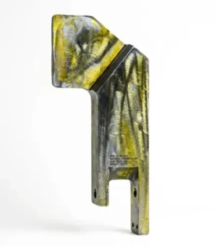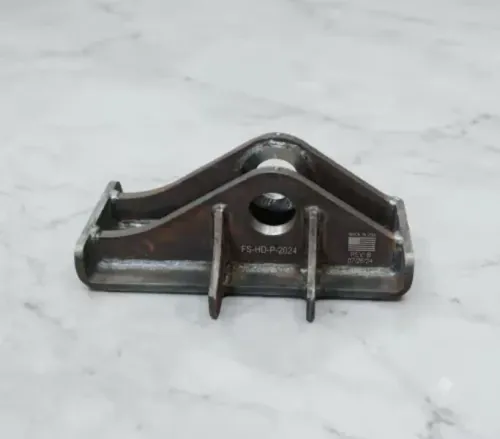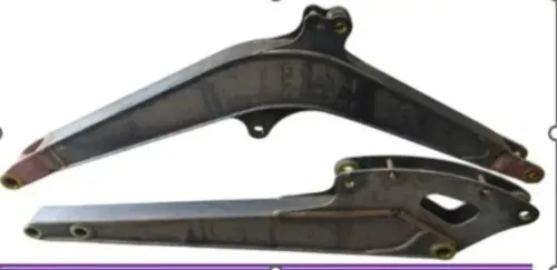
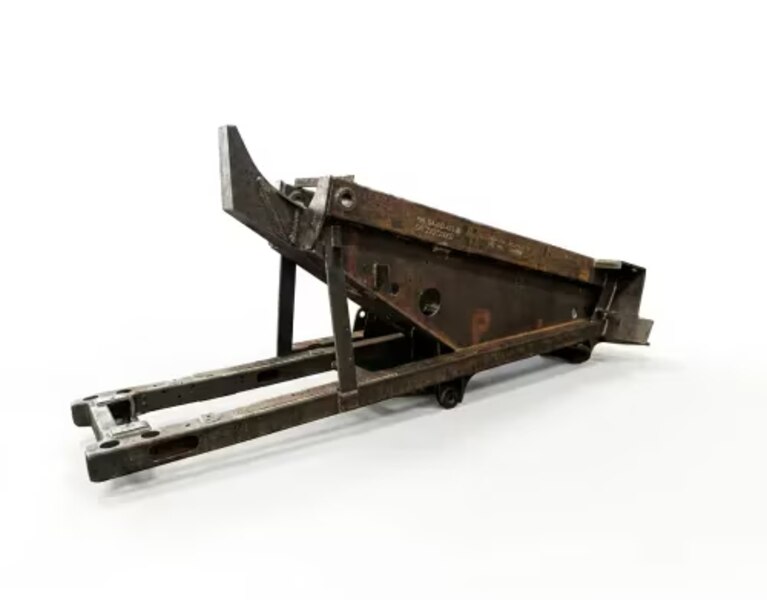
A steering arm transfers steering input from the knuckle, axle beam, or steering gear to a tie rod or drag link, so a small error in its geometry can change steering angle, toe behaviour, clearance, and fatigue life. By the end, you will know which dimensions, materials, validation tests, quality records, and supplier capabilities to check before approving a part for an OEM machine.
Key takeaways
- Confirm mounting datums, hole patterns, offsets, and tie-rod geometry before production.
- Match material and heat treatment to steering load, fatigue, and corrosion exposure.
- Request drawing revision, CAD model, sample measurements, and validation records.
- Compare suppliers on traceability, inspection capacity, repeatability, and production readiness.
How a Steering Arm Carries Steering Load Through an OEM System
A steering arm converts steering input into lateral movement at the tie rod or drag link. Bolted or integrated at the steering knuckle, spindle, or axle beam, it carries torque from that support into the linkage; in a steering-gear layout, the gear output reaches the arm through a pitman arm and drag link.
Its joint location fixes the Ackermann relationship between inner and outer wheel angles, while the arm length influences steering ratio and required steering effort. Incorrect geometry changes toe behaviour through the steering sweep, causes tyre scrub, or makes the steering stop contact too early.
Check the arm and linkage through full suspension travel, including articulation, bump, rebound, and maximum lock.
- Tractors: low-speed tyre scrub, axle articulation, mud and water demand robust joints and protected interfaces.
- Loaders and earthmoving machines: high steering force, bucket-induced reactions, shock loading, vibration, and abrasive contamination dominate.
- Construction equipment: repeated impact, uneven ground, mud, and water challenge fatigue life and corrosion protection.
- Mining equipment: extreme joint loads, abrasive dust, severe vibration, and long duty cycles require conservative fatigue validation.
- Commercial vehicles: road-speed stability, production repeatability, steering precision, and controlled toe change receive greater emphasis.
Specify the actual force path, wheel loads, steering stops, lock angles, duty cycles, and contamination exposure before approving a steering arm for OEM equipment. A static load check proves resistance to one applied force; it does not establish fatigue suitability under repeated steering cycles, shock, vibration, or changing toe loads.
Qualification needs representative cyclic testing and post-test crack and deformation inspection.
The Drawing Dimensions That Decide Whether the Arm Fits
Before requesting a quotation, freeze the interfaces that locate and steer the part. Confirm the mounting-hole pattern, hole and bore diameters, centre-to-centre dimensions, mounting-face relationships, offsets, handedness, envelope clearance, steering angle, and steering-stop locations.
| Feature group | Confirm on the drawing | Why it matters |
|---|---|---|
| Mounting interface | Hole pattern, diameters, bore sizes, face relationships, offsets | Prevents assembly mismatch and unwanted clamp distortion |
| Linkage interface | Joint-axis location, angular position, taper orientation, engagement length | Preserves Ackermann geometry, toe behaviour, and steering ratio |
| Vehicle clearance | Envelope through suspension travel, steering angle, stop locations | Prevents contact before the designed steering limit |
| Manufacturing detail | Fillet radii, surface finish, burr limits, and geometric tolerances | Controls fatigue notches, joint seating, and repeatable motion |
Specify a tie-rod or drag-link taper by taper geometry, major and minor diameters, engagement length, and seating condition. Nominal thread size identifies the fastener thread, not the stud seat; maximum hole diameter does not prove taper interchangeability. A wrong taper can bottom out, leave inadequate seating, or shift under steering load.
Use functional datums from the knuckle or axle mounting interface, then control the linkage-joint axis relative to those datums. A precision steering arm manufacturer should report position, orientation, runout, perpendicularity, and profile tolerances with CMM results or dedicated functional gauges.
The drawing must distinguish assembly controls from dynamics-critical controls: a steering arm for OEM equipment can have correct hole sizes yet still alter steering behaviour through an incorrect axis, offset, angular position, or mounting-face relationship.
Material, Manufacturing Route, and Validation for the Actual Duty Cycle
Choose the route against duty-cycle fatigue, volume, and geometry—not nominal strength alone.
| Route | Strengths | Limits and best use |
|---|---|---|
| Forged steel | Directional grain flow, strong fatigue performance, repeatable high-volume production, near-net shapes | Requires dies and tooling; best for established, demanding programs |
| Qualified ductile iron or other cast grade | Complex near-net shapes and less machining; economical at suitable volumes | Porosity, shrinkage, inclusions, and grade control demand strict foundry qualification |
| Machined-from-solid billet | Fast design changes, no forging die, useful for prototypes and low volumes | High material removal and machining cost; billet grain structure does not reproduce a qualified forging’s fatigue behaviour |
A precision steering arm manufacturer should trace every part to its material grade and heat-treatment lot. Verify hardness or tensile results, then inspect forgings for laps and seams, castings for shrinkage, porosity, and inclusions, and finished parts for sharp tool marks, uncontrolled radii, burrs, and machining-induced notches at bosses, fillets, and bores.
- Require stress analysis using the equipment manufacturer’s loads, followed by static proof or overload testing.
- Run cyclic fatigue testing to the specified loads and cycles; a generic catalogue value is not qualification.
- Check joint interfaces, including taper seating, bore fit, fastener seating, and clearance through motion.
- After testing, inspect for cracks and measure permanent deformation against drawing limits.
Weld repair is an OEM-approved exception, not a routine correction. Permit it only under a qualified welding procedure with controlled preheat, filler, welder approval, and follow-up inspection suited to the material and fatigue risk.
What to Request When the Part Comes From a Drawing, CAD Model, or Sample
Require a controlled drawing or CAD model before production release; a sample or part number alone cannot define revision, material condition, critical characteristics, or approval status.
| Source | What it controls | Risk if used alone |
|---|---|---|
| Customer drawing | Dimensions, datums, tolerances, material and revision | Missing manufacturing intent or outdated revision |
| 3D CAD model | Geometry, interfaces and envelope | PMI, material and approval status may be absent |
| Reverse-engineered sample | Physical fit and visible features | Hidden heat treatment, tolerances and fatigue requirements remain unknown |
| Existing part number | Identity and purchasing history | Variant, revision or superseded specification may be unclear |
Release the steering arm only after collecting:
- First article inspection report and dimensional inspection report, including CMM results against functional datums based on the knuckle or axle interface.
- Material test certificate, material-lot record, heat-treatment condition, and hardness results.
- Process flow, control plan, capability data for critical features, and current calibration records for measuring equipment.
- Batch traceability from blank receipt through machining, heat treatment, surface treatment, inspection, and packing.
Use dedicated taper gauges and functional gauges for linkage interfaces; disconnected measurements from arbitrary outer surfaces can pass while the assembled joint binds or misaligns. Periodically check the arm in the assembled interface, not only on a fixture.
Define an engineering-change process requiring OEM approval before changes to material, tooling, process, supplier, or revision. Record nonconformance disposition, specify corrosion protection, and retain approved samples with revision, batch number, and retention period. An automotive steering arm supplier should also provide approval status and change history for every production batch.
How to Compare a Steering-Arm Supplier in Chakan for OEM Production
Strength claims do not prove OEM readiness. Compare evidence of repeatability across batches, capacity at your required takt time, and control from blank receipt through packing, not merely the machining centre list.
- Ask who owns forging or casting dies, machining fixtures, gauges, and replacement schedules; inspect fixture-maintenance records.
- Check CMM availability, calibrated dedicated taper and functional gauges, metallurgical laboratory access, and fatigue-test access.
- Verify qualified forging or casting sources, heat-treatment charts, hardness or tensile results, surface-treatment records, and material-lot traceability.
- Review sub-supplier audits, nonconformance history, packing specifications, on-time batch performance, and backup plans for heat treatment, coating, power loss, or source failure.
Program type changes the acceptance burden.
| Program | Production and approval emphasis | Service exposure |
|---|---|---|
| Automotive steering arm supplier | High takt-time capacity, statistical capability for critical features, formal first-article and production-part approval records, corrosion controls | Repeated production volumes and tightly controlled assembly variation |
| Heavy-equipment steering arm | Demonstrated overload and fatigue performance at larger joint loads, stronger containment of process variation | Shock, mud, water, abrasive contamination, and low-speed tyre scrub |
Assess Pranav Heavy Industries Private Limited as a steering arm manufacturer in Chakan by requesting process-flow and control plans, revision history, calibration records, traceability, inspection capacity, and dated delivery results. Require design-specific static, fatigue, and interface validation; generic “precision” or “durability” language is not acceptance evidence.
Also ask how weld repairs, engineering changes, rejected batches, and emergency supply are authorised and documented.
Related product
 | Steering Arm Pranav Heavy Industries Private Limited manufactures high-quality Steering Arms engineered for precision, strength, and long-lasting performance. View product → |
Frequently asked questions
Which drawing dimensions determine whether a steering arm fits?
Check mounting-hole diameter and spacing, locating features, arm offset, tie-rod or drag-link taper, joint angle, thickness, datum scheme, and allowable tolerances.
How should you select material and manufacturing route for a steering arm?
Select material, forging or fabrication route, heat treatment, machining sequence, and surface protection against the arm’s steering loads, fatigue duty, impact exposure, and corrosion environment.
What should you request when sourcing a steering arm from a drawing, CAD model, or sample?
Request the latest drawing revision, native or neutral CAD file, material and heat-treatment specification, critical tolerances, inspection plan, sample measurement report, and validation evidence.
How can you compare a steering-arm supplier in Chakan?
Compare machining and fabrication capability, fixture control, CMM or gauge inspection, material traceability, process documentation, batch repeatability, corrective-action practice, and OEM production capacity.
Keywords