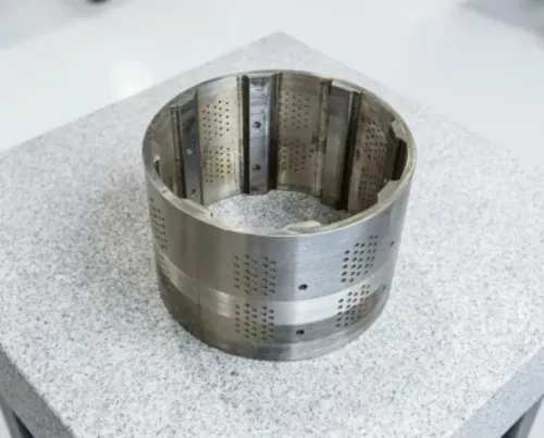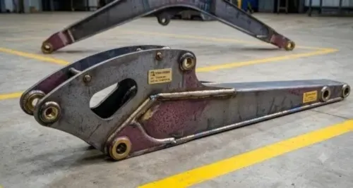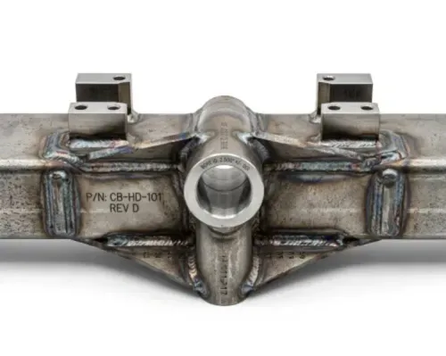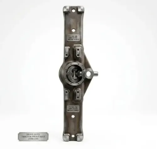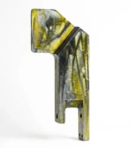
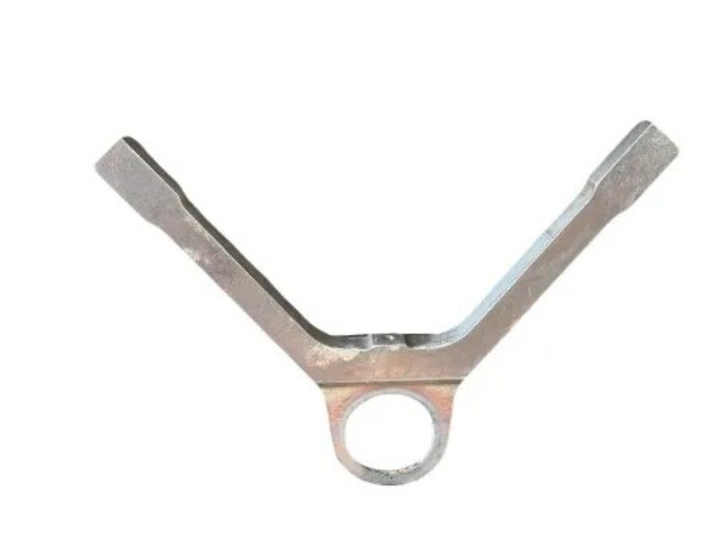
The better production route depends on the UCA’s load path, joint geometry, tolerance scheme, material, quantity, and inspection burden—not on the word “precision” in a quotation. By comparing fabrication and machining against those factors, you can choose a process that controls fatigue risk without paying for unnecessary material removal or rework.
Key takeaways
- Choose fabrication for welded load paths, complex profiles, and lower production volumes.
- Choose machining when tight tolerances, consistent bores, and repeatability justify extra stock.
- Use a hybrid route for welded structures requiring precision-machined interfaces.
- Specify weld locations, datum schemes, bore tolerances, flatness, and inspection records.
How fabrication and machining create different UCA designs
The plate UCA fabricated or machined decision follows the geometry and production situation, not the acronym. A fabricated UCA component is profiled from plate, formed or fitted from separate pieces, welded into a load-carrying shell, then finish-machined at critical bores and faces.
It suits large or irregular profiles, internal voids, simple flat geometry, welded ribs or gussets, and low-to-medium quantities because it removes less material than machining a mostly hollow arm from a block.
| Route | How the UCA is made | Best fit |
|---|---|---|
| Fabricated | Profiled plate and fitted pieces are welded, then critical interfaces are machined | Large or irregular arms, internal voids, ribs, gussets, and lower-to-medium quantities |
| Machined | Solid plate or a near-net blank is cut into the arm profile, pockets, mounting faces, and joint interfaces | Repeat production requiring stable datums, accurate bore location, concentricity, and minimal weld distortion |
Machining earns its extra stock and cycle time when one controlled setup must preserve pivot bores, bearing seats, parallel faces, or datum relationships. Fabrication avoids extensive stock removal but introduces weld distortion and inspection requirements.
Compare both routes using the same drawing revision and functional requirements. “UCA” alone is not a procurement description: an upper control arm may be welded, forged, cast, or machined. Request the load cases, bush or ball-joint design, joint interfaces, fatigue duty cycle, mass target, material grade, and corrosion-protection requirement before comparing quotations.
When a fabricated UCA is the stronger production choice
Cutting and welding provide the sounder technical and economic route when a fabricated UCA component has weld-accessible joints, adequate edge distance, gussets, bend or cut geometry, and a weldable steel grade.
The route suits large or irregular profiles, internal voids, and low-to-medium quantities because it uses less stock than machining a hollow arm from a large block.
| Route | Strong choice when | Main control |
|---|---|---|
| Fabrication | The arm has simple plates, gussets, and reachable joints | Qualified welding procedure and distortion plan |
| Machining | Bores, faces, and datums require tight positional control | Stable fixturing and controlled roughing and finishing |
| Fabrication plus machining | The shell is economical to weld but interfaces must be precise | Finish-machine bores and mounting faces after welding |
Confirm that an electrode or torch can reach every joint and that inspectors can see and test each weld. Provide drainage, venting, coating access, and a method to remove spatter or slag; trapped contamination will undermine corrosion protection.
Welding can pull mounting faces out of parallel, move bores from the arm centreline, create residual stress, alter heat-affected-zone hardness, and distort high-restraint joints. Control it with a rigid fixture, balanced sequencing, heat-input and interpass-temperature limits, and a qualified procedure.
Calculate preheat from steel grade, carbon equivalent, thickness, restraint, hydrogen control, and the procedure—not from a universal temperature.
Plan finish machining after welding where the drawing permits. Inspect more than appearance:
- Check dimensions and datums.
- Use magnetic-particle or dye-penetrant testing for surface-breaking flaws.
- Use ultrasonic or radiographic testing when penetration or internal discontinuities matter.
Weld-toe undercut, lack of fusion, incomplete penetration, and abrupt starts or stops can control fatigue life more than plate yield strength.
When machining from plate justifies the extra stock and cycle time
Choose a machined plate UCA when pivot-bore location, reamed holes, bearing seats, parallel mounting faces, concentricity, or datum relationships carry more risk than material and cycle-time savings.
| Route | Dimensional advantage | Main cost or risk | Best fit |
|---|---|---|---|
| Machined plate UCA | Controlled bores, flatness, concentricity, and datum relationships | High stock removal, longer machining, larger fixtures, and higher scrap exposure | Low volume with high dimensional risk; repeat batches with simple tooling |
| Fabricated UCA | Near-net shell with critical interfaces finish-machined | Weld distortion, weld inspection, residual stress, and post-weld machining | Large sections, internal voids, irregular profiles, and higher material utilisation |
Producing critical geometry in one controlled setup can improve bore location and repeatability while removing weld distortion from the main process. It does not remove the need for dimensional inspection.
Check cutter access before approving the route. A deep pocket can be impossible to reach, and a starting plate larger than machine travel can disqualify machining regardless of tolerance. The plate and fixturing also cost more.
Quenched-and-tempered or highly stressed plate can move after roughing as residual stress is released. Ask for a process that includes:
- Rough machining and the proposed stock allowance
- Stress relaxation where material, thickness, and tolerance justify it
- Finish machining of datums and bores in a controlled sequence
- Tool-access review, fixture concept, and expected cycle time
Compare actual quantities, not piece prices alone. Fabrication usually wins for large, hollow, or heavily reinforced arms; machining earns its premium when weld access is poor and dimensional failure threatens the assembly.
Which drawing and inspection details should decide the route
The released drawing, not a generic process label, should decide the route. Request its revision, material grade and condition, load cases, fatigue requirement, weld symbols, datum scheme, surface finishes, coating system, and inspection plan before comparing quotations.
| Feature | What to verify | Route implication |
|---|---|---|
| Profile | Outside contour and profile tolerance | A broad profile tolerance does not compensate for a misplaced pivot bore. |
| Functional interfaces | Bore location, face flatness, parallelism, concentricity, and datum relationships | Tight ISO 1101 controls favour machining or post-weld machining. |
| General dimensions | Whether the drawing invokes ISO 2768 or ISO 2768-2, including tolerance class and feature scope | Do not apply either standard where the released drawing does not invoke it. |
Use ISO 1101 when the drawing assigns explicit position, parallelism, flatness, or profile tolerances. Ask the plate UCA supplier to state whether each feature is checked by CMM, gauges, bore measurement, fixture inspection, or a first-off report.
For fabrication, require evidence for the complete control chain:
- Qualified welding procedures and welder qualifications
- Material certificates, heat traceability, cutting records, and dimensional reports
- Weld NDT reports naming the method and acceptance level: magnetic-particle or dye-penetrant for surface flaws, ultrasonic or radiographic testing for critical internal discontinuities
- Calibration records, coating records, and change-control commitments
ISO 3834 helps assess welding quality controls; it does not prove fatigue strength. A buyer evaluating a plate uca manufacturer in chakan, including Pranav Heavy Industries Private Limited, should compare repeat-batch capability, distortion controls, post-weld machining, and documented acceptance results rather than one sample part.
Related product
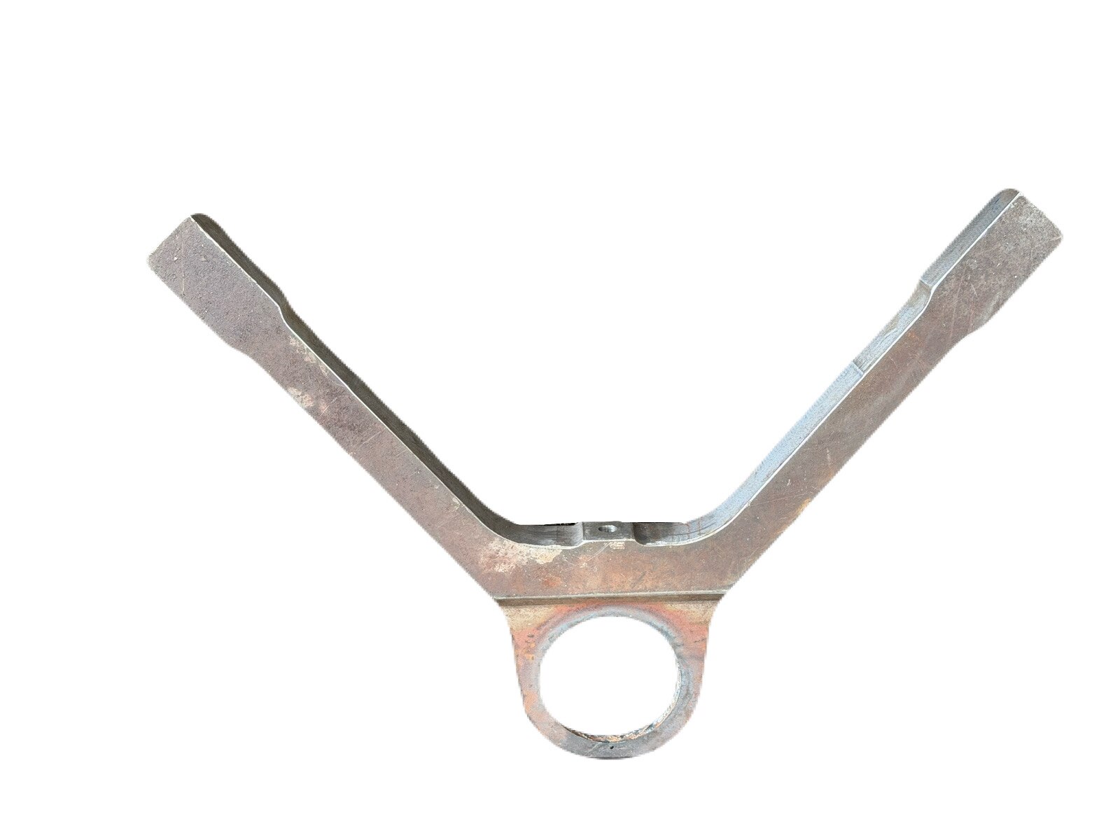 | Plate UCA UCA Plate (Upper Control Arm Plate) is a precision-fabricated and machined component generally used in automotive, earthmoving, construction... View product → |
A practical rule for choosing fabrication, machining, or a hybrid route
Choose fabrication when weld-accessible plates and gussets carry the load, the steel grade is weldable under a qualified procedure, and the profile is large or irregular. Choose machining when bore location, bearing seats, parallel faces, concentricity, or datum relationships control performance.
| Route | Choose it when | Main control burden |
|---|---|---|
| Fabrication | Large or irregular profiles, internal voids, lower-to-medium quantities, and material savings matter | Fixture rigidity, weld sequence, heat input, NDT, distortion correction, and post-weld machining |
| Machining | Critical interfaces dominate and cutters can reach the shape without excessive stock removal | Plate size, stock waste, residual-stress movement, fixturing, tool access, and cycle time |
| Hybrid | The shell is economical to cut and weld, but pivot, bearing, pin, or mounting interfaces need precision | Stabilise weld distortion before finish-machining functional datums and bores |
A hybrid route is often the balanced choice. Fabrication creates the near-net load-carrying structure; machining then establishes the interfaces that determine assembly alignment.
Compare plate UCA fabricated or machined routes against static strength, fatigue duty cycle, mass, corrosion protection, repairability, lead time, tooling, NDT, post-weld stress relief, finish machining, and rejected assemblies. A machined plate UCA is not cheaper merely because it avoids weld inspection, and a fabricated arm is not economical if distortion causes repeated rework.
Before awarding work, ask the plate UCA supplier for:
- A process flow covering cutting, welding, stress relief, roughing, and finish machining.
- A feature-by-feature acceptance plan for bore-to-datum position, parallelism, and thermal-cut edges.
- A total-cost comparison including fixtures, inspection, correction, and scrap.
The better process meets the released drawing at the lowest controlled total cost, not the shortest operation list.
Frequently asked questions
How do fabrication and machining create different UCA designs?
Fabrication builds the UCA from profiled or formed plate pieces joined by welds, while machining cuts the component from solid plate stock. Fabricated designs suit welded shells and assembled load paths; machined plate UCAs provide continuous material around critical features.
When is a fabricated UCA the stronger production choice?
Choose a fabricated UCA when the design contains large welded sections, formed walls, complex profiles, or low-to-medium production volumes. It can reduce material removal and support economical structural construction when weld distortion is controlled.
When does machining a UCA from plate justify extra stock and cycle time?
Choose a machined plate UCA when the drawing demands tight bore alignment, controlled flatness, consistent datums, or repeatable geometry across many parts. The route makes sense when machining time and material waste are outweighed by interface accuracy and inspection confidence.
Which drawing and inspection details should decide the manufacturing route?
Review material grade, plate thickness, weld symbols, bore diameter and position tolerances, datum references, flatness, perpendicularity, surface finish, heat treatment, and inspection requirements. These details reveal whether welding, machining, or both are needed.
Keywords